| |
|||||||||
| |
|
|
|
|
|
|
|
||
| Home | About | Literature | Site Map | MSDS | Contact | Engineers | Shows | Links | Samples | RFQ | Catalog Numbers |
Problem:
A 4,800-foot duct bank runs from one campus building to another. You plan to install a fiber optic cable in an empty conduit in the bank. The run goes through a number of turns and manholes. Can you safely make the installation in a single pull, or must the cable be pulled out, figure-eighted, and then pulled back in for the rest of the run?
Problem:
You're installing shielded, twisted pair data cable with a maximum pulling tension of 55 lbs (245 Newtons). Part of the run is into a 550-foot (165 meters) conduit under a concrete factory floor. It is a straight conduit run, with a stub up at one end. Can you make the pull with less then 55 lbs (245 Newtons) force? Which end of the run is it best to feed the cable into?
Problem:
There's an 8,300-foot (2530 meters) underbridge crossing. You want to install a "preducted" fiber optic cable (cable extruded in innerduct) into an existing FRE® conduit. The recommended maximum load for the thick walled duct is 4,500 lbs (20 kN). Will the run be easy, hard, or impossible? You should know before you start the pull . . .
Finding the Answers
The situations above were all real field problems. While the cable types and specifics are quite different, all three do have something in common!! In all three, "Cable Pulling Theory" can help answer the questions and provide a sound basis for planning the installation.
"Cable Pulling Theory" allows us to estimate pulling tension when cable is pulled into conduit. The theory is based on physical laws. In this case, the force required to move an object across a surface is equal to the force between the surfaces times their coefficient of friction.
In cable pulling, the cable becomes "the object" and the conduit "the surface." The forces depend on both gravitational weight and the "pressing" force from pulling cable around bends. The end result is a series of equations that require specific input on cable weight; conduit length and direction; location of bends; and the coefficient of friction between cable jacket, conduit, and pulling lubricant.
Know Your Limits
"Cable Pulling Theory" will do you no good, however, unless you know the maximum force you can put on the cable without risking damage to it. This maximum tension varies significantly with the type, construction, and size of cable.
Lightweight coaxial and shielded data cables can have allowable tensions as low as 30 - 50 lbs (135 - 235 N). Larger outside-plant fiber optic cables with strength members are usually in the 400 to 800 lbs (1.8 to 3.6 kN) maximum load range. Allowable tension on innerducts can vary from 500 lbs (2.2 kN) to 5,000 lbs (22 kN), depending on the wall thickness and reinforcing members. The maximum tension for multi-pair copper cable is determined from the number and gauge of the conductors.
All cables have tension limits, and some cables also have sidewall pressure (tension going around a bend) limits. Look for these limits on the cable's spec sheet. If you don't find anything there, consult the cable manufacturer. The cable manufacturer is just as interested in having the cable properly installed, and avoiding damage during installation as the installer is.
What's Your Guess?
To further illustrate, which direction would you pull to get the lowest tension in the conduit diagrammed below--from A to C or C to A?
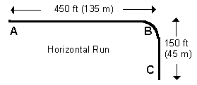
The correct answer is C to A, but why?
To answer this question, we need to look at a simplified form of the pulling equations (given below):
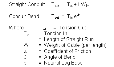
In the first equation, we see that straight sections add the same amount to incoming tension regardless of which direction we're pulling. Any difference in tension with direction would come from the bend at B. We see from the second equation that bends multiply the incoming tension. If we start the pull at C, the tension when we get to bend B is less, so the result of multiplying it adds less then if we were pulling the other direction. Thus, pulling from C to A will give lower tension than from A to C.
In this simple example, "Cable Pulling Theory" has answered a very practical field question: "Which direction should we pull?"
Huh?
Once you know the tension limits of the cable, or how much force you can use to pull without risking damage, you're ready for calculations using the full pulling equations, rather than the simplified versions above. Unfortunately, the full pulling equations are complex. They have numerous terms, including hyperbolic functions. Because each conduit segment builds on the one before it, working them with a calculator is cumbersome. But a PC works great!!
Software Solutions
American Polywater's Pull-Planner™ 3000 Program calculates pulling tension, conduit fill, jam ratios, and sidewall pressure for a cable pull. It allows quick changes of conduit system design, incoming reel tension, coefficient of friction, pulling direction, and cable parameters. It can even take a measured tension from an actual pull and calculate the coefficient of friction, which can then be used in calculations for similar jobs.
The Pull-Planner™ 3000 Software makes it possible to analyze complex pulls quickly and easily. You can plan operations by looking at "what if" options with various field parameters.
Saving Time and Money
One of the earlier examples involved an underbridge pull of 1.25" (32 mm) high tensile duct with a 144 fiber cable preducted. The high tensile duct could be pulled with up to 4,500 lbs (20 kN). It was being installed with three empty 1.25" (32 mm) ducts into a 5" (127 mm) FRE® conduit. A rough sketch of the underbridge conduit system is shown below:
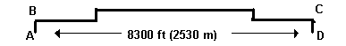
The first set of calculations, even with the extremely low coefficient of friction from Polywater® J, showed tensions above the maximum on a pull from A to D.
Additional calculations, however, showed that pulling the duct in at B and out at C (avoiding the two end bends), and then back-feeding through the short vertical runs, should make the long pull possible with under 4,500 lbs (20 kN).
The pull was completed successfully this way, with an actual monitored tension of 3,900 lbs (17 kN). The result? A complex installation was planned and completed safely and efficiently using the Pull-Planner™ 3000, and, of course, the low friction possible with Polywater® J. The money and time savings from such an effort are obvious.
Summary
Excess tension can damage cable and/or reduce its life. Many cable pulls do not require the detailed analysis possible with the Pull-Planner™ 3000 Software. But for difficult or complex pulls, the software is a powerful tool for planning safe, high quality installations.
Ordering Information
The Pull-Planner™ 3000 is an inexpensive and useful piece of software. Price only $129.00. Click here to order.
View this article in PDF Format
For more information, check out our Program Preview
View a 12-minute training video on Fiber Optic Cable Pulling & Lubrication
For Subscriptions, Comments, or Questions contact: tteditor@polywater.com
Home |
About |
Site Map |
Literature |
Samples |
Links |
Reps |
Videos |
Pumps |
RFQ
Codes |
Engineering |
Shows |
Spotlight |
Newsletters |
MSDS |
Translations |
Contacts |
Jobs

11222 60th ST N | Stillwater, MN 55082-9310 USA
1-(651) 430-2270 (Voice) | 1-(651) 430-3634 (Fax)
1-(800) 328-9384 (Toll-Free US/Canada Only)
Copyright © 2001 - 2015 American Polywater Corporation | ![]() 6/5/15
6/5/15