
 | Home | Products | Representatives | Resources | SDS | Contact |
| Polywater Support Page |
A Study of Automatic Lubricant Application in Cable Pulling
| John M. Fee American Polywater Corp PO Box 53 Stillwater, MN 55082 USA |
Dale P. Solheid American Polywater Corp PO Box 53 Stillwater, MN 55082 USA |
Abstract: Lubricant application rates are determined for typical, heavy cable pulling. The parameters affecting lubricant flow rate through pumps are examined theoretically and experimentally. Lubricant viscosity, pump pressure, feed hose size, and feed hose length are studied. These data are used to develop guidelines for cable installers interested in pursuing automatic lubricant application.
Keywords: Cable Pulling; Pulling Lubricants; Automatic Lubrication; Pumping; Flow Rate; Pressure Pot
I. INTRODUCTION
The use of specialty lubricants to reduce cable pulling tension is common. These materials are called cable pulling lubricants or cable pulling compounds.
The usual method of applying pulling lubricants is "by hand." The lubricant is either poured into an upturned conduit or patted onto the advancing cable jacket throughout the pull. The job is messy, and once a worker has lubricant on his hands, he can't do much else. A lengthy cable pull can take well over an hour, and even the most conscientious worker can tire and the consistency and quality of lubrication can suffer.
Construction crews who regularly install large amounts of cable are interested in ways to automatically apply pulling lubricant. This can not only free-up a worker, but can also insure consistency and optimization.
However, because they are non-newtonian fluids, cable pulling lubricants are not always "easy" to pump. Commercial lubricants vary in viscosity from liquids (a few hundred centipoise) intended for pouring into an upturned duct to thick gels or pastes (over 90,000 cps) intended for hand lifting and overhead application.
Additionally, pulling lubricants may contain high molecular weight polymers that make them slippery and cause them to cling to the cable jacket as the cable moves through the conduit. These polymers are often shear sensitive. That means the lubricant can lose its friction reducing and cling properties if it is subjected to high-shear while running through a pump.
It does not make sense to select a pumping system that neccessitates the use of a poor performing pulling lubricant. Rather, the best automatic lubrication systems will use pumps that can pump a variety of the best performing pulling lubricants from various manufacturers. The considerations for designing such a system are reviewed in this paper.
II. BODY
Lubrication Rate For Cable Pulling
The amount of lubricant needed for a cable pull can be described by:
Q = K x L x D (1)
| Where: |
| Q = Quantity of lubricant in liters (gals) |
| L = Length of conduit in meters (feet) |
| D = ID of the conduit in mm (in) |
| K = Constant ranging from 4 to 8 x 10⁻⁴ (metric) or 0.8 to 1.6 x 10⁻³ (English) |
The derivation of Equation (1) is relatively straightforward. It represents the amount of lubricant needed to completely coat the interior of a conduit with a lubricant film of 0.1 to 0.2 mm thickness (0.005 to 0.009 inches). Equation (1) calculates lubricant quantities consistent with those used by experienced cable pulling crews.
Equation (1) is easily converted into a lubrication rate calculation:
R = K x D x S (2)
| Where: |
| R = Lubrication rate in liters/min. (gals/min.) |
| S = Pulling speed in meters/min. (feet/min.) |
At typical underground pulling speeds of 3 to 20 m/min. (10 to 60 ft/min.) and duct sizes of 50 to 150 mm (2 to 6 inches), Equation (2) provides expected lubricant demand from 0.06 to 2.4 l/min. (0.02 to 0.6 gal/min.). Such low volume flow rates can be produced by a number of different low-power pumps.
Based on these calculations, the pumping tests will focus on producing and controlling flow rates from 0.05 to 2.5 l/min. (0.02 to 0.6 gal/min.). While not necessary during pulling, it is convenient to have a large volume capability of 12 to 20 l/min. (3 to 5 gal/min.) for occasional fast lubricant loading into a conduit for prelubrication.
Theory of Laminar Liquid Flow Through a Pipe
The Hagen-Poiseuille Equation [Reference 1] predicts laminar, incompressible liquid flow through a circular tube as:
![]() (3)
(3)
| Where: |
| Q = Liquid flow rate |
| pdif = Pressure differential |
| D = Pipe interior diameter |
| µ = Liquid viscosity |
| L = Length of pipe |
If the pulling compounds behave as incompressible liquids with laminar flow, Equation (3) predicts that:
Pressure Pot Pump Mechanics
The studies in this paper were done with a "pressure pot" style pump. A pressure pot moves a liquid by using a compressed air head over the liquid inside a pressure vessel. While common in industrial spraying operations, pressure pots are not often used as large scale pumps. However, they have some very useful features for field pumping of cable pulling lubricants.
A pressure pot has no moving parts, and thus requires minimal maintenance. Air compressors to "power" the pot are readily available in the field. Very small compressors are suitable, since the actual air volume required to support a pull is very low, usually less than 0.1 m³/hr (< 3 cfh).
In a pressure pot, there is no shear on the lubricant since there are no blades, paddles, etc. moving through the lubricant. This allows the use of a restriction valve to control flow rather than the need to "slow down" a positive displacement style mechanical pump.
For this study, the pot head pressure was controlled with a regulator on the compressed air feed to the pot. Early in the study we discovered that relatively low pressures (< 1.5 bars or 20 psi) would pump the less viscous lubricants at flow rates much higher than needed. For tests where this was the case, a second pressure gauge that would accurately read lower pressures was installed.
An industrial pressure pot (Devilbiss Type QMG) designed to hold a five gallon (19.4 liter) pail was used for the study. The dip tube was increased to 19 mm (3/4 inch) to eliminate any restrictions in the pot.
The other variables were studied by changing the lubricant (viscosity) in the pot or changing the hose coming from the pot (feed hose interior diameter and length)
Flow Rate Versus Incoming Pressure
Figure 1 shows flow rate in l/min. versus head pressure in bars. The lubricant pumped was 18,000 cps viscosity (Brookfield spindle #6 @ 10 rpm) and the feed hose was 19mm (3/4 inch) ID and 6.1 m (20 feet) in length (horizontal). The hose was left open so the flow was the maximum the head pressure would provide.
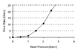
Fig 1. Lubricant Flow Rate Versus Head Pressure
The flow rates shown in Figure 1 were not measured past 3.5 bars (50 psi) of head pressure. 3.5 bars produced a flow rate of almost 40 l/min., well above the highest calculated demand.
Lower pressure data measured with the more sensitive pressure gauge are shown in Figure 2.
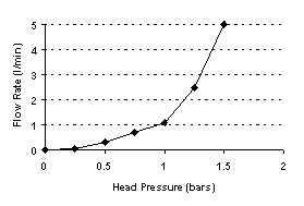
Fig 2. Lubricant Flow Rate Versus Low Pressure
Figure 2 shows that less than 1.5 bar (20 psi) produces sufficient flow to support the top end of our target operating range of 2.5 l/min. (with this 18,000 cps lubricant and 6 m length of 19mm hose).
Changing air pressure is not the best or most practical way to control flow rate. When set at 1.5 bar (20 psi), we found a ball or gate valve on the line could easily meter the flow to the low end rate desired (0.05 l/min.). This technique provided a consistent low level lubricant flow without pulsing or surging.
Figures 1 & 2 show roughly linear behavior below 1 bar pressure and above 1 bar head pressure, but with different slopes on the curves. We believe this difference results from the pseudo-plasticity (non-newtonian liquid behavior) of these pulling lubricants. High polymer lubricants often show a higher viscosity when still or under low shear than they do under turbulent high shear conditions. Equation (3) shows that a decrease in viscosity at higher flow rates (higher shear) would cause the curve slope to increase at these higher rates. This was what was observed.
Flow Rate Versus Lubricant Viscosity
Figures 3 & 4 expand the graphs of Figures 1 & 2 by running through a typical range of pulling lubricant viscosities. The hose length and ID were 6.1 m and 19 mm as in the previous test. For perspective, at the high end, a 98,000 cps lubricant is a thick gel that cannot be poured. The low end 2,700 cps lube is a liquid that pours easily through a 25 mm (1 in) orifice.
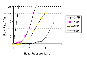
Fig 3. Flow Rates for Differing Viscosity Lubricants
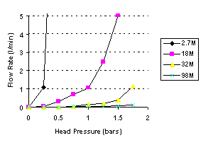
Fig 4. Low End Flow Rates at Differing Viscosities
With the estimate of 2.5 l/min. as the high end flow needed to support cable pulling. Figure 3 shows that even the most viscous gel lubes can be pumped at this rate with a pressure head of less than 4 bars (60 psi). With the proper pumping system, a broad range of lubricant viscosities can be pumped.
Figure 4 shows that the liquid lubricant (2,700 cps) requires minimal head pressure for adequate flow. We see that 0.25 bar (4 psi) is more than enough for this hose length and diameter. The thicker liquid lubricant (18,000 cps) requires less than 1.5 bars (20 psi) for a sufficient feed rate.
For equipment design purposes, Figures 3 & 4 can be used to establish the maximum pressure head needed to cover all pulling situations. The lubricant flow can then be metered down through a restriction valve as needed for a specific installation.
Figures 3 & 4 qualitatively follow the theory in Equation (3), that is, the less viscous the lube, the faster it pumps. However, the agreement is only rough quantitatively. The theoretical expectation is that halving the viscosity doubles the flow (inverse proportionality). The non-newtonian nature of these fluids probably accounts for the variation.
Flow Rate Versus Hose ID
An important design criteria for a pumping system is the size of the hose (or pipe) used to carry the lubricant to the cable, conduit, feeder tube, etc. Figure 5 shows flow rates with the 18,000 cps lubricant and a 6 meter (20 feet) horizontal hose with 3 different feed hose interior diameters. The ID's were the 19 mm (3/4") used for the previous study, 12 mm (1/2") and 9.5 mm (3/8").
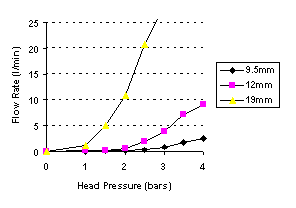
Figure 5. Flow Rate vs Hose Sizes for 18,000 cps Lube
Figure 5 shows that the head pressure to maintain a 2.5 l/min. flow through a 6.1 m (20 ft) hose is 1.5 bar (20 psi), 2.7 bar (40 psi), and 4 bar (60 psi) for the 19 mm, 12 mm, and 9.5 mm hoses respectively. The data follows the D4 in Equation (3) reasonably well. This predicts that, when the other variables are constant, the 12mm hose will have flow 2.5 times the 9.5 mm hose and the 19 mm hose will support 6 times as much flow as the 12 mm hose.
Figure 6 presents the same data for the least viscous 2,700 cps lube.
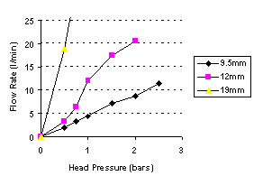
Figure 6. Flow Rate vs Hose ID for 2,700 cps Lube
Figure 6 shows that with the 2,700 cps lube, less than 0.75 bar (10 psi) is required to pump lube at 2.5 l/min., even with the small 9.5 mm (3/8") hose.
Flow Rate Versus Hose Length
Figure 7 shows lubricant flow rate as a function of total feed hose length. The length of hose is usually dictated by field considerations. It is a question of how close you can get the pump, which is often mounted on a truck, to the cable feed point. The 6.1 m (20 ft) used for the measurements in the previous graphs would be suitable in most field situations. Figure 7 uses hose lengths double and half the 6.1 m (at the horizontal) to analyze the effects of this variable (with the 19 mm hose). The lubricant used is the 18,000 cps viscosity.
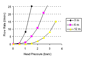
Figure 7. Flow Rate Vs Hose Length
Figure 7 shows hose length to be a more significant effect than the theory indicated. The flow is reduced by a factor of 5 or more when the hose length is doubled. But even with the 40 foot hose, it took less than 2.5 bar (35 psi) to pump sufficient lube for cable pulling.
Other Types of Pumps
While the data in this research was generated from a pressure pot pump, it can provide guidelines for systems using other types of pumps. Many pump types will move liquids of these viscosities, and easily create the pressures and flows required. The usual problem is to get a pump with enough draw to pull the liquid into the pump. A pressure pot, in a sense, has all the liquid in the pump, so priming, feed-flow and cavitation are not issues.
Pumps can be powered electrically, hydraulically, or pneumatically. It is desirable to use a pump that does not shear the lube or build high pressure in the feed hose when flow is reduced with a restriction valve. Low ratio piston-type grease pumps and air-operated diaphragm pumps meet these criteria.
While positive displacement pumps that push the lubricant through in chunks (paddle, peristaltic, sine, moyno) have minimal shear, it is better to control pumping rate in this type of pump by slowing down the displacement speed (number of chunks) rather than restricting the output line and pumping against a head.
High shear pumps that run at a high constant speed (rotary vane, gear) are usually not appropriate for field lubrication. The continuous shear from the blades causes deterioration in lubricant performance and builds high pressure in the feed lines.
III. CONCLUSIONS
Flow rates of 0.05 to 2.5 l/min (0.02 to 0.6 gal/min) are shown to be adequate for automatic lubrication in most cable pulling situations, with rates of 12 to 20 l/min (3 to 5 gal/min) recommended for bulk transfer.
Pressure pot pumps can pump a broad range of lubricant viscosities at satisfactory rates. A head pressure of 0.25 bar (4 psi) is satisfactory for low viscosity (2700 cps) lubricants, with 4 bars (60 psi) working for a high viscosity (80,000 cps) lube.
Hose and hard piping ID are shown to be critical in volume flows. The data indicate that at least a 19 mm hose should be used, especially when pumping high viscosity lubricants.
The total length of feed hose is also shown to be a significant factor. The feed hose should be kept to the minimum length possible while still being functional.
IV. REFERENCES
[1] Victor L. Streeter, E. Benjamin Wylie, "Fluid Mechanics," Eighth Edition, McGraw Hill, 1985
V. BIOGRAPHIES
John M. Fee received a B.S. degree in chemistry from Massachusetts Institute of Technology in 1968. He worked from 1968 to 1981 at the 3M Company, St Paul, MN on a variety of product development projects. Since 1981, he has been with American Polywater, and is currently President. He has worked extensively in the area of cable pulling and its theory. Mr. Fee is a member of the ICC and the PES, and chaired the working group which developed IEEE Standard 1210.
Dale P. Solheid received a B.S. in Chemical Engineering from the University of Minnesota in 1995. Mr. Solheid worked at American Polwater on a variety of chemical products used in electrical and telephone construction. His work included the engineering of pumping systems to move the large volumes of liquids typical in chemical processing.
Click here to Add Your Name To Our Mail List
View free streaming videos on Cable Pulling Lubrication

This website uses third party cookies to analyze navigation and to improve the quality of the user experience. Address: 11222 60th Street N, Stillwater, MN 55082, USA Phone: +1 651 430-2270 | Fax: +1 651 430-3634 | Phone: 800 328-9384 (Toll-Free USA/Canada) General Email: Email Contact Page |